
JMRI CDI Primer
There are two versions of a CDI (Configuration Description Information) that can be used to configure RR-CirKits nodes. One is the JMRI CDI version and the other is the Deepsoft CDI version. This primer is only applicable to the JMRI CDI version.
The reader may notice that there are many LCC components acknowledged on the OpenLCB.COM web site. The non-RR-CirKits components seen there are focused on advanced LCC devices within the DIY community and you should not be intimidated by them. After you get established with LCC, you can venture into the DIY world if you desire. For this document, we will focus on off-the-shelf components from RR-CirKIts.
The CDI is a vital link in setting up your LCC system but it can be very intimidating to a person creating their first LCC. It was set up as a convenient way to load all the data to the system and it works well for that. However, it lacks refinements that would make data entry easier for a new person. The manuals for the components in the network have a well written set of instructions for the details required to load data but they present the information with an expectation that a user will already understand many features of the CDI. For a new LCC user, that typically is not true. If you have looked at the manuals and are trying to figure out how to load all that information into the CDI, this guide is to help you make a step toward using the manuals effectively.
In general, a reader should have the Tower LCC and Signal LCC manual handy when reading this document. At the time this was written, the latest manuals were Feb 2019 for the Tower LCC (complete manual) and Apr 2018 for the Signal LCC (partial manual). The latest versions are available for download from the RR-CirKits web page.
This is NOT intended to replace the manual. Instead, it is intended as a supplement to help a new person get familiar with how the CDI is structured and some of the features used by the CDI so they can get more value out of the manual.
Menu overview
The CDI will offer you a convenient way to load the multitude of data element required to set up the Signal LCC and Tower LCC nodes. When you first open a CDI, you will see a very long form that will initially look strange, intimidating and overwhelming. The first thing we need to do is to compress that long form down to its basic menu lines only. That will allow you to see that it is actually a group of individual forms. Each form has a specific purpose and can stand alone to meet its own purpose yet they interconnect to exchange information to get their individual jobs done.
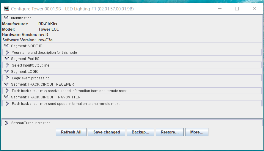
Below is the compressed CDI menu for the Tower LCC board.
Below is the compressed CDI menu for the Signal LCC board.
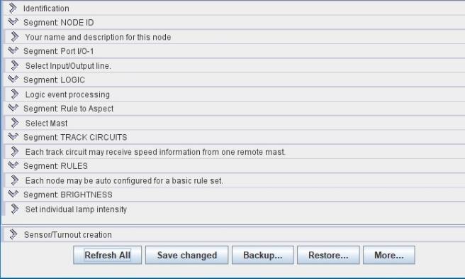
Each line in the menu is called a “segment”. Expanding each segment will reveal the form that you will populate with the data element required to set up the node. Looking at the manuals will show you what each segment looks like when expanded. Note that the CDI’s have some common segment titles as well as some differences. That is because each has some common feature as well as unique features to each node. As an example, the Signal LCC is a host for signal drivers and is used to setup signal’s while the Tower LCC does not have that capability.
Data fields
There are several types of data fields and each one requires a different approach.
Plain text field – A plain text field can contain any information you want to insert. Typically, it is a place for you to insert some type of identification for your own benefit and to include some documentation. Some of these type fields will also take your input and add it to a tab above it so that information will stand out on the tab. Plain text fields are not used in any calculations or logic.
Drop down field – A drop down field will display the list of valid options for you to choose from for entry into that field.
EventID field – This is often the most difficult entry for new people because they do not understand what it is. As noted elsewhere, the EventID is simply a code that is used to communicate that “an event happened”. Strangely, the EventID has no meaning on its own and only has meaning when you assign it a meaning and put it in the right context. Example- Bob lives at 2145. Obviously, an address but it has no meaning without the full address. This is typically a big stumbling block for new people. The EventID is actually a long hexadecimal number such as 02.01.57.00.01.9B.02.12. By itself, it has no meaning but if a “producer” says “02.01.57.00.01.9B.02.12 means turnout #44 has been thrown”, then that EventID suddenly has meaning. That means that a “consumer” somewhere on the networks can receive and use that information to make something happen. Example – that EventID may be the trigger to tell another node somewhere on the network to change a signal from green to red. As you can see, this EventID is the language used between nodes on the networks.
To use this EventID language, you will need to insert the EventID into many different fields in the CDI forms. Do not worry about typing all these numbers. The CDI has some tools in the CDI that will allow you to copy/paste the EventID’s very easily without typing all those numbers.
Buttons
There are many different buttons in the CDI and they all offer shortcuts to make it easier for you to input data with minimal error via a simple button push. Other that the buttons at the bottom of the CDI, all buttons only apply to the field they are co-located with.
- Refresh – This button will retrieve the currently stored value on the node and place it in the data field. Handy if you start typing something then decided to go back to the original date.
- Write – Writes the data value to the node. This action MUST be done when you have finished editing the data field otherwise the data value will never be stored in the node. Once you have written the new data, the old data is lost. A refresh will just show you the data you had most recently written.
- Copy – This button will copy the hex number currently showing and hold it in memory until you decide to paste it somewhere else. This is how you link different data fields in the CDI together so that will both be using that EventID for the same purpose.
- Paste – This button will paste the EventID (hex number that you have in memory) into this data field. This field will already have an EventID in it that you will be overwriting. Once you paste it and Write it, this field is now linked to a specific EventID that it can use as needed.
- Search – When you hit the search button, a data field will open next to it. This will allow you to search for an item (turnout, sensor, etc) using a name you are familiar with rather than a long hex string. As you type, a list will show up and may change the more you type and get closer to the name you are searching for. When the item you want to pick shows up, select it and the EventID (hex number) for the item you selected will show up in the EventID field. Don’t forget to Write the new EventID you just loaded.
- Make Sensor – Use this to make a sensor from EventID’s that represent some specific activity. After you copy/paste the EventID’s into the Active/Thrown and the Inactive/Closed field, hit the Make Sensor button and the CDI will create a sensor that represents the Active/Inactive state for whatever EventID’s you used. Example – it you use a block occupancy device to sense if a block was occupied (active) or unoccupied (inactive), then used those EventID to build the sensor, the sensor would be able to report the occupied/unoccupied status of the block. Another example would be a pushbutton. The system name created here is actually the two EventID’s separated by a semicolon such as:
- 02.01.57.00.01.9B.02.12; 02.01.57.00.01.9B.02.13
- Make Turnout – Identical to the Make Sensor except that this does it for a turnout and represents the thrown (Active) and closed (Inactiver) state of the turnout.
- Refresh All – This button operated just like all the other Refresh buttons except that it does a universal refresh for all data fields.
The following buttons are all at the bottom of the CDI.
- Save changed – Similar to a Write. This will cause all changes to be saved to the node if they were otherwise unsaved. Convenient way to make sure you saved all your data entries. Forgetting to save a data entry is a common error for new and old users. See the hints below for another way to help avoid this error.
- Backup -Triggers a backup of your node to your computer. The backup can be used later to restore the node data set back to the node.
- Restore – Triggers the CDI to restore the backup you have on your computer onto your node.
- More > Reboot – Causes the node to reboot itself just as if you had started it from scratch. Handy if you think some data may be corrupted and wanted to make sure you had a clean start.
- More > Update Complete – Not needed with this current generation of components. This button will allow some future generation of nodes to be updated with multiple updates at a time.
- More > Make all Sensors – Allows you to reset all the I/O lines as sensors rather than do them one at a time.
- More > Make all Turnouts – Allows you to reset all the I/O lines as turnouts rather than do them one at a time.
General guidelines and tips
Many of these are covered in the manuals but may be easy to miss for a new user:
- Outputs and Inputs are relative to the node. A node Outputs signals to a daughter card and receives Inputs from a daughter card.
- Normally, a node card come from the manufacture with the data field already set up to receive Inputs from a daughter card thus is easier to set up for inputs like from a block occupancy card. If you want to use it to make Outputs to drive external items, you will need to change the data values in a number of fields.
- Logic rules are structured to test for a True outcome first and drop to the next level if False. This means that when you do conditionals, you are asking if it is True (not False). In this way, you can test for more constrained situations first and then if they are not true, your logic will trickle down to the lower levels until it hit a True conditional.
- Many segments of the CDI use tabs as a way to store information in equivalent but separate forms at the same level. The tabs may have names like Line 1/2/3/4/5/6/7/8, Event 1/2/3/4/5/6 and Logic 1/2/3 through 32. Each tab has an identical form but represents a different set of data. One tab may represent the logic with one situation while the next represents the logic for a different situation. Every tab is active in the CDI even though you do not see all them at the same time.
- Once you start loading EventID’s into the true/false fields of the logic, you will notice that a list will start building under the true/false fields that show where that same EventID was used elsewhere in that CDI. The CDI does this automatically. As the list builds, it can be used as a diagnostic tool. Example – to see where a name pops up that you did not expect so you can track down the error.
- You may note some (C) and (P) notations in some locations. That indicates that the line is a Consumer (C) or a Producer (P) of EventID’s
- Each node has 32 logic cells to work with but if you run out of logic cells on one node, you can extend your logic work to another node (see manual)
- A group of logic cells can be on any node. They not need to be on the same node that is hosting the activities (such as a signal mast) it is working on. Example – logic cells are calculating signal aspects but the signal mast actually resides on a different node.
- When you make a change to a data field, it will go into effect immediately as soon as you “Write” it.
- The CDI does not know what choices you need to make for data entries. It will accept whatever you input – right or wrong and happily go forward and make its calculations. It will not tell you where you made an error. You must look at various clues and do your own detective work to find out why something came out wrong.
- The CDI does not automatically save anything. For anything to become permanent, you must use the Write button.
- When you get a new node, do a backup. This will allow you to go back to the beginning if you determine that you have messed up your data and need to restore the node to new.
- When you get a new node, check to make sure it has the latest updates that are shown on the RR-CirKits web page. If not, download them and update your nodes before you start working with them.
- It is easy to forget to save a data entry even though the field is highlighted in a strong orange color. You can change the reminder feature to be more persistent by showing a color all the way to the top level if something has been changed but not saved. This is done as following:
- In PanelPro, got to Edit > Preferences > display > GUI
- Then select the radio button for “Metal”.
- This will change the color appearance of your JMRI window but will also cause the CDI to highlight data changes you failed to save.