
RR_duino – Emmanuel
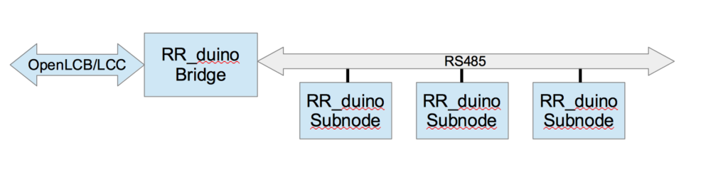
RR_duino refers to firmware for Arduino and software on a computer that lets a set of Arduino communicate over RS485 (similar to CMRI), but appear as full nodes to OpenLCB/LCC . This local network is master-slave. Software on a PC enables these subnodes to appear as full nodes to OpenLCB/LCC by acting as a Bridge, and managing CDI and Event handling, etc.
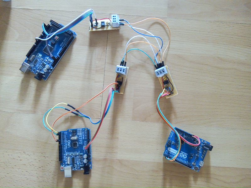
Here are three Arduino boards communicating over RS485. The smaller boards contain RS485 drivers.
Short introduction from the implementer:
RR_duino is a “sketch” for arduinos that enable them to control turnouts (using servo for positioning and also having position feedback and optional relay control for changing frog polarity), simple outputs (OFF/ON like CMRI for example) or simple inputs.
All this can be controlled using a binary wire protocol described here:https://github.com/manu-fwi/RR-duino/blob/master/RR-DUINO-protocol.odt
The typical setup would be to have several RR_duino nodes on a RS485 bus each having a different address (<127 IIRC) all being controlled by one controller.
All RR_duino nodes runs the RR_duino sketch but the controller must dispatch any command it receives from outside by putting it as an RR_duino message and send it on the bus.
For now only one controller is available as a client that connects to the openlcb-gateway, transforming each RR_duino node as an openlcb node.
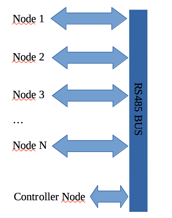
Controller node may be a computer (Raspberry Pi, PC) or any capable MCU.
All setup is done using the RR_duino protocol (pins configuration and even bus address setting, but also fine tune the servo positioning for each turnout) ; no need to reflash any node to change its setup, a python script enables you to do that via a text UI : https://github.com/manu-fwi/RR-duino/blob/master/pico-rr-duino-setup.py
Moreover the controller may communicate to other nodes or JMRI for example using OpenLCB through a gateway (a python script exists : https://github.com/manu-fwi/openlcb-gateway).
Example of a node from start to use :
- controller asks the node version (to check if the node is up) : if no answer before timeout node is not up otherwise proceed to 2.
- controller asks the node to load its config from eeprom (this will also set all outputs ports to the state saved in eeprom, and set turnout to their last known position).
- Controller can ask the node to send it its full config (this is used by the openlcb gateway to build the CDI accordingly for example).
- Now node is up and well known by the controller just send commands : put turnout of subaddress 2 of node 3 to thrown position, put output of subaddress 5 of node 1 to 0, read changed inputs from node 4 (all nodes pile up the input changes until someone retrieves them).
RR_duino Wiki: https://github.com/manu-fwi/RR-duino/wiki
Gateway Wiki: https://github.com/manu-fwi/openlcb-gateway/wiki